top of page
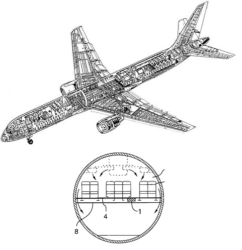
The Problem
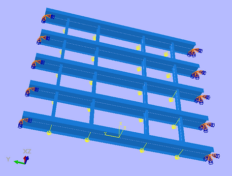
For this problem, I used Abaqus to model a section of an aircraft floor, using 5 beams for the floor track, perpendicular to 4 moment continuous beams for the seat track. Both sets of I beams had a given cross section, and loads were given to be 1000 and 1500 lbf
Setup
The floor section was 5 100 inch long floor beams spaced 20 inches apart, with 4 moment continuous tracks at Y = -35, -15, 15, 35. Both sets of beams had different cross sections. Loads were directly applied at each node, in the -z direction.
Two different boundary conditions were tested: pinned ends (rotation about x) and fixed ends. This was done because for this floor section, the actual boundary conditions exist somewhere between fixed and pinned, so I tested both to determine the worst case outcome
Results
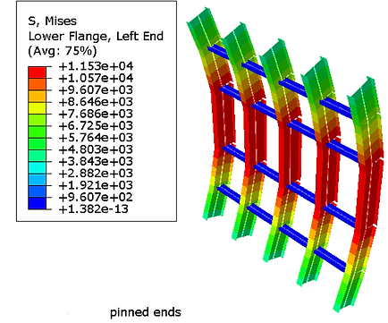
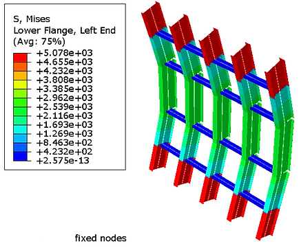
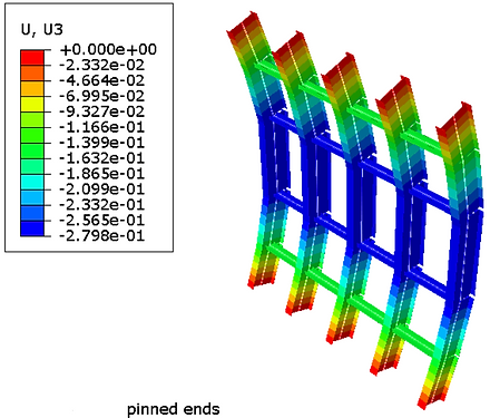
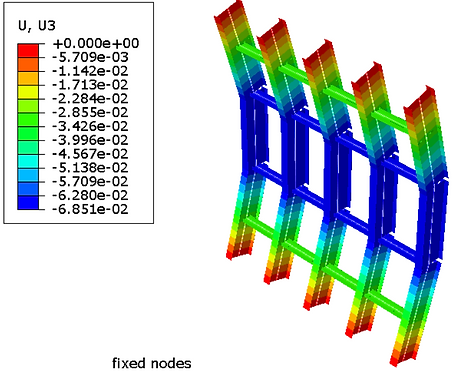
Above are the results for von mises stress for pinned (left) and fixed (right) ends. The chosen material was Aluminum (linear elastic), which has a yield strength of 40,000 psi. It appears safe to determine deformation using linear elastic testing, as the stress in both cases doesn't approach yield stress, and as such are in the elastic region. From the above charts, a factor of safety of 3.46 and 7.88 exist for the pinned and fixed end setups respectively. Additionally, there is a displacement of -0.28 and -0.069 inches for the pinned and fixed ends respectively, in the z direction
bottom of page